Translate page: |  |  |  |  |  |  |  |  |
Translate page: | | | | | | | | |
The MU-1800-I is a single axis, digital tilt sensor used to report the angle of an object with respect to gravity. Optical shaft encoder technology provides a full +/- 180 (360) degree range. A code wheel and an LED light source comprise the heart of the MU-1800-I. Integral to the MU-1800-I is a weight which is attached to one side of the code wheel assembly causing it to remain stationary with respect to gravity. Internal magnetic damping assures fast response time while eliminating oscillations and ringing. As the housing moves relative to the codewheel, the moving image of radial lines is converted to a real-time digital signal.
The MU-1800-I is a non-contacting, rotary to digital converter that converts real-time shaft angle and direction into a digital signal that is displayed on the AP3 front panel. It utilizes an extremely rugged mylar disk, LED light source, metal shaft and high quality ball bearings. The unit is powered by the AP3 digital display unit, and operates on +5VDC.
The rotary to digital converter uses a transmissive optical encoder module which has a lensed LED source and a monolithic detector IC enclosed in a small polymer package. The module uses phased array detector technology to provide superior performance and greater tolerances over traditional aperture mask type encoders.
|
|
||||||||||||||||||
| Vibration | 20 g. 5 to 2KHz |
| Weight | 8.47 oz. |
The MU-1800-I utilizes eddy-current damping technology. Please refer to the following chart and notice the difference between zero damping and the MU-1800-I damping (angle measurements are obtained immediately and without ringing).
The AP3 is a digital LCD readout designed to display the incremental count value of the MU-1800-I. The AP3 features a sign indicator for displaying both positive and negative angles. Signals from the MU-1800-I are filtered to ensure signal integrity over the entire input frequency range. The Match LED illuminates and relay closure occurs when an encoder count equals the zero angle. Under normal operation the relay closure feature is not needed. However the modeler may want to connect an external light or audio enunciation indicating zero angle has been reached. Please refer to the mechanical drawings and electrical specifications for proper implementation of this feature. Note that any angle reported by the MU-1800-I can be reset to a zero reference angle.
The AP3 Digital Display is powered by the AP12, +12 Volt power supply (included- see below). Optionally, the display unit accepts power from an external battery through a standard 2.1mm DIN circular plug (see FAQ Page for further details). The AP3 Digital Display supplies the +5 VDC power for the MU-1800-I.
Whenever the preprogrammed limits of +/- 0.5 degrees are exceeded, the AP3 digital display illuminates a corresponding High or Low LED. This feature is quite useful since it lets the user know when the angle is approaching zero.
The AP3 is constructed of a lightweight high impact polymer case with a clear viewing window. The AP3 display offers 0.5" high digits with blue backlighting. Leading Zero Blanking provides superior readability! (New, October 2006). The AP3 front panel thickness may range up to a maximum of 0.125" thick.
Note: It is very important that care be exercised when opening the case. Do not touch any of the electrical components as static discharge can damage them. Do not force the AP3 into an undersize cutout or over-tighten the screws when reinstalling the case. Damage resulting from improper installation is not covered under the terms of the AeroPerfect™ Warranty.
| Parameter | Min. | Typ. | Max. | Units |
| Supply Voltage | 7.5 | - | 30 | Volts |
| Supply Current* | - | - | 40 | mA |
| Encoder Input Cycle Frequency | - | - | 1.2 | MHz |
| Relay Contact Rating*** | - | - | 3.0 | Amps |
| Relay Switching Rating**** | - - | - - | 125 24 | VAC VDC |
| Relay Dielectric Stength | 500 | - | - | VAC |
| Relay Contact Resistance | - | - | 100 | uOhms |
| Enocder Output Voltage** | 4.8 | 5.0 | 5.2 | VDC |
| Encoder Supply Current | - | - | 250 | mA |
| Encoder Low Input | - | 0.4 | 0.8 | VDC |
| Encoder High Input | 2.0 | 5.0 | 5.75 | VDC |
The AP-12 is an 18W regulated switching power supply that provides 12VDC @ 1.5A output. The power supply covers voltage inputs ranging from 90 to 264VAC and 47 to 63Hz which accommodates most international power requirements. Typical efficiency is 70% and output is short circuit protected.
The power supply DC output uses a 2.1mm circular plug (center positive) which is attached to a 48 inch long cable. The power supply plugs directly into a standard 120VAC receptacle or the appropriate AC plug adapter (see below).
| Input Voltage | 90 to 264VAC |
| Input Frequency | 47 to 63Hz |
| AC Plug Type | 2-Prong, USA Type, non-polarized |
| Output Voltage | 12VDC |
| DC Output Plug | 5.5 x 2.1 x 9.5 mm female barrel, center positive |
| Load Regulation | ±5% |
| Ripple & Noise | 40mV maximum |
| Operating Temperature | 0 to 40°C |
| Storage Temperature | -30 to 80°C |
| Protections | Over voltage, Over current and Short circuit |
| Certification | UL 1950, CB (per EN 60950) |
| EMI | Meets FCC class "B" |
| AC Input Indicator | Green LED |
| Size (inches) | 3.15 x 2.16 x 1.26 (WLH) |
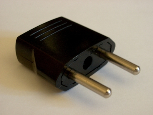
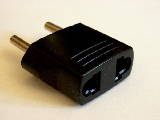
(Click Thumbnails for Larger Picture) |
|||||
(European to U.S. Plug Adapter) |
|||||
|
|
||||
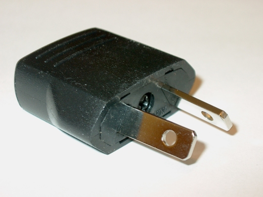
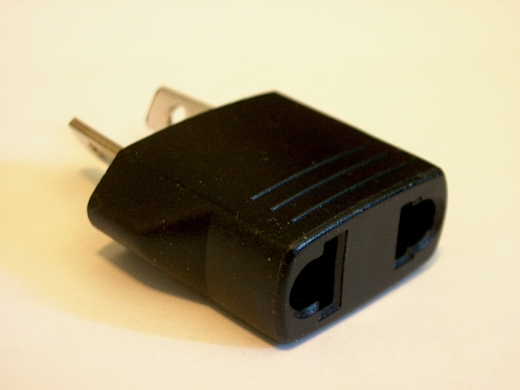
(Click Thumbnails for Larger Picture) |
|||||
(Australian to U.S. Plug Adapter) |
|||||
|
|
||||
© 2004 - 2008, Bell Electronic Technologies All Rights Reserved