Translate this page into:


Translate this page into: | | | | | | | | | |

How many times have we drilled control horn mounting holes in our tapered control surfaces only to find the holes in the wrong location on the opposite side? Often times the holes on the opposite side end up either too close or too far away from the hinge line which sometimes makes it impossible to attach the control horn backing plate without taking drastic measures!
Enter the AeroPerfect™ MU-9000X USB! No more guess work because you can maintain the correct drilling angle and come out right every time! The following procedure details drilling control horn mounting holes in an aileron using a pin vise.
Please refer to the procedure below.
(Click Thumbnails for Larger Picture) |
||
(Turn off Pop-up Blocking) |
|
|
|
(Click Thumbnails for Larger Picture) |
||
(Turn off Pop-up Blocking) |
|
|
|
Step 1
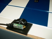
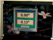
Start out by placing your wing / aileron on a flat surface. From the "Main View", establish a zero reference angle on the flat surface and click "Zero" (left and middle photos, top row). Select "Large Digit View".
Step 2
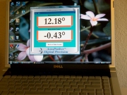
Measure the taper angle of your aileron (right photo, top row and left photo, bottom row). The aileron taper angle in this example measures 12.18°. Click on "Back to Main Screen".
Step 3
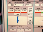
Divide that angle in half: 6.09°. Place the MU-9000X measuring plate on the flat surface (as in step 1) and lift up the edge of the measuring plate (closest to the aileron) until the display reads 6.09°.
Step 4
While holding the measuring plate at 6.09°, click the -90 button. This establishes the zero angle reference for drilling with the hand-held pin vise. To check your reference, you can place the measuring plate onto the aileron (as in step 2), the angle should read -83.91° because -90.00° + 6.09° = -83.91°. Since in our example the plate wasn't held exactly at 6.09°, we got a reading of -83.88° when we put the measuring plate back on the aileron (middle photo, bottom row). This is close enough for drilling with a hand-held pin vise (within 0.03°). Select "Large Digit View".
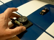
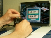
Step 5
Hold the measuring plate against the pin vise (right photo, bottom row). Make sure the rotational axis of the pin vise is parallel to the flat surface of the measuring plate. Drill into the aileron while maintaining a drilling angle of 0.00°. Use the drop-down "Target Tolerance" menu to set when the green color bar comes on. This helps in holding the drill angle. In this example, the tolerance is set to 0.25°. Make frequent corrections and only twist the pin vise while the reading is 0.00°. The holes on the opposite side of the aileron will come out right every time!
Note:
In the example above, if you wanted to hold the measuring plate against the other side of the pin vise (on the opposite side to that shown in the middle photo, bottom row), you would hold the measuring plate at 6.09° and click the +90 button instead. Again, as in step 4, this establishes the zero angle reference for drilling with the hand-held pin vise. To check the reference, you can place the measuring plate onto the aileron. The angle should read +96.09°. You can now hold the measuring plate against the pin vise and drill while maintaining 0.00°.
HAPPY FLYING!
© 2004 - 2008, Bell Electronic Technologies All Rights Reserved