
Measuring angles of incidence and/or decalage with your AeroPerfect™ Digital Control Throw Meter is a breeze! Because a zero reference angle can be set anywhere you choose, setting up your glider or aerobatic plane has never been easier!
Please take a look at AeroPerfect's new MU-9000X USB which uses your laptop or desktop PC to measure angles with a resolution of 0.01 degrees!
(Click Thumbnails for Larger Picture) |
|||||
(Turn off Pop-up Blocking) |
|||||
|
|
||||
First, just a bit of background: The angle of incidence of the airplane's wing is the angular measurement between a reference line on the plane's fuselage (sometimes called FRL for "Fuselage Reference Line" or WL for "Water Line") and the wing's chord. The wing's chord, by definition, runs through the wing's cross section from the center of the leading edge to the tip of the trailing edge. The same also applies to the angle of incidence of the airplane's horizontal stabilizer. It is the angular measurement between the FRL and the horizontal stabilizer's chord.
Decalage (deka-laj) is a word of French origin and refers to the angular difference between the wing's chord and the horizontal stabilizer's chord and does not reference the FRL or WL line. Positive decalage means that the wing is at a more nose-up angle than the tail. As an example, if the wing has an incidence of one degree leading edge up and the tail an incidence of one degree leading edge down (or "negative one degree"), there is a decalage of positive two degrees. If the wing is mounted with an incidence of positive five degrees and the tail with an incidence of positive three degrees, the decalage is still two degrees positive.
Measurement Preparations
In order to measure decalage or incidence, you will need to hold your aircraft securely in place and level the wings (an eyeball estimate is all that is required). An incidence clamp is required in order to get a reference line that is parallel to the wing chord. You can build your own or use one of the several commercially available ones.
Measuring Decalage
Step 1:
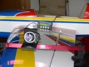
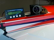
Turn your radio and receiver on and adjust the elevator for zero deflection. Simply secure the incidence clamp to the stabilizer and hold the MU-1800-I's measuring plate onto the top of the crossbar. Push the RESET button on the AP3 Digital Display to set a zero reference angle.
(Click Thumbnails for Larger Picture) |
|||||
(Turn off Pop-up Blocking) |
|||||
|
|
||||
Step 2:
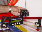
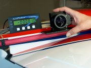
Remove the incidence clamp from the stabilizer. If it's necessary for the clamp to be on the aileron, use the aileron servo to hold zero deflection. Secure the incidence clamp to the wing. Again, hold the MU-1800-I's measuring plate onto the top of the crossbar. Maintain the original zero-set orientation. Read the decalage angle directly from the AP3 Digital Display. In the above photos, you'll notice that the wing's chord is slightly more "nose down" than the elevator's chord.
Measuring Incidence
The method for measuring Incidence is fundamentally the same as for measuring decalage, except the AeroPerfect's zero reference angle is set at the FRL (or WL).
Step 1:
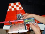
Identify the FRL (or WL) and hold the edge of the MU-1800-I's measuring plate parallel to it. For example, let's assume the FRL is parallel to the top portion of the fuselage where the canopy would go. Place the MU-1800-I's measuring plate onto the top portion of the fuselage as shown. Push the RESET button on the AP3 Digital Display to set a zero reference angle.
|
|
|
||||||
(Click Thumbnails for Larger Picture) |
||||||||
(Turn off Pop-up Blocking) |
||||||||
Wing's Angle of Incidence
Step 2:
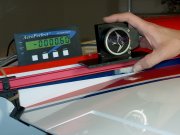
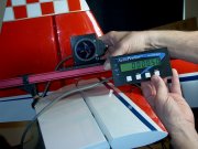
Secure the incidence clamp to the wing. Hold the MU-1800-I's measuring plate onto the top of the crossbar. Maintain the original zero-set orientation. Read the wing's angle of incidence in relation to the FRL directly from the AP3 Digital Display.
Stabilizer's Angle of Incidence
Step 3:
With the elevator servo holding zero, secure the incidence clamp to the stabilizer. Hold the MU-1800-I's measuring plate onto the top of the crossbar. Again, maintain the original zero-set orientation. Read the stabilizer's angle of incidence in relation to the FRL directly from the AP3 Digital Display. You can see that the difference between the two incidences (the wing's incidence in relation to the FRL and the stabilizer's incidence in relation to the FRL) is .60 degrees. This is exactly what we measured for the decalage. Obviously, if you're interested in measuring decalage, it is best to use the method described under "Measuring Decalage" because it only requires two measurements instead of three.
Take note of where you obtain your zero angle references and notice whether the angles are moving positive or negative.
HAPPY FLYING!
© 2004 - 2008, Bell Electronic Technologies All Rights Reserved