
|
|
|
||||||
Click Thumbnails for Larger Picture |
||||||||
(Turn off Pop-up Blocking) |
||||||||
The AeroPerfect™ Digital Control Throw Meter makes setting up your rudder throws a cinch! In the following example, the rudder control throws are setup for +/- 28.65 degrees. If your aircraft's control throws are specified in inches or millimeters, these numbers are easily converted to degrees here. Also, the new AeroPerfect™ MU-9000X USB has a built in utility for converting from inches to millimeters!
Make sure your aircraft is held so it can't move around. You can make your own cradle or there are a number of commercially available cradles you can use. Adjust your aircraft's position so that the rudder's hinge line is reasonably level (eyeball is fine).
Step 1:
Adjust your rudder linkages as you normally would. If your rudder will be driven by two servos, make sure you attach only the linkages associated with the servo you're setting up. Move the rudder to its neutral position. You can either employ a method of mechanically clamping the rudder at neutral or use your radio and servo to hold it in position.
Step 2:
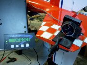
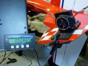
Either hand hold or clamp the MU-1800-I to the rudder so that the edge of the measuring plate is near the hinge line and parallel to it. Place your AP3 Digital Display where you can view it while you make control throw adjustments. (In order to get the AeroPerfect™ AP3 into the photo, it is clamped to a music stand, but you can place it anywhere within a 6 foot radius from the MU-1800-I for easy viewing!) Simply push the RESET button on the AP3 Digital Display to set a zero reference angle.
Step 3:
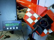
Push your radio's stick fully to the left and then fully to the right while using your AeroPerfect™ to measure the control throw angles. Obtain the desired control throw angles either by adjusting your radio's EPA's, or mechanically adjusting your linkages. If you plan to program Hitec Digital Servos to obtain your control throws, please see the Hitec Digital Servo Programming Page.
(Optional Step 4)
Setting up your control throws using a second rudder servo is easy with the AeroPerfect™. Unclamp and temporarily remove the MU-1800-I from the rudder. Rotate your aircraft axially 180 degrees so that the opposite side of the rudder is facing up. Adjust your aircraft's position so that the hinge line is reasonably level (again, eyeball is good enough). Disconnect the linkage from the servo you setup in steps 1 - 3.
(Optional Step 5)
Adjust the rudder linkage for this servo exactly as you did the first one. Move the rudder to its neutral position. As in step 1, employ a method of holding the rudder at neutral in preparation for the next step. Again, as in step 2, either hand hold or clamp your MU-1800-I to the rudder so that the edge of the measuring plate is near the hinge line and parallel to it. Push the RESET button on the AP3 Digital Display to set a zero reference angle.
(Optional Step 6)
Repeat the procedure used in step 3 for setting up the rudder control throws associated with this servo and its linkage. Once you get the same control throws for this servo and its linkages, (make sure they're operating in the correct direction before proceeding) you can connect the linkages associated with the first servo. Again, if you plan to program Hitec Digital Servos to obtain your control throws, please see the Hitec Digital Servo Programming Page. Since two digital servos are operating one control surface, it is recommended that you adjust the deadbands on both servos to be the same (and perhaps a bit wider than default). Use the AeroPerfect™ to verify the control throws with both servos operating.
HAPPY FLYING!
© 2004 - 2008, Bell Electronic Technologies All Rights Reserved